Page 2
Continuing with the process of building the horizontal tail, the focus now moves to the elevator. As was mentioned previously, there appeared to be a discrepancy with the elevator spar locations so getting to the root of the problem and coming up with a solution became the primary consideration at this point of the project. I had several discussions with the factory as well as with other builders and developed a plan of attack that would work. While this was going on there was another small discrepancy that needed dealing with, and the following details the process of what I did to keep from having this part of the project come to a screeching halt waiting for me to come to a final decision about what to do with those spars. |
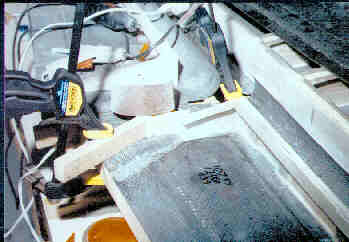
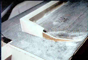
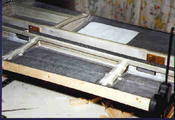
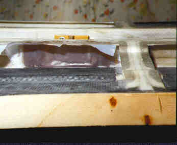
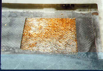
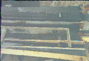
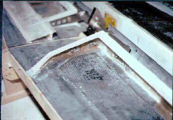
Fixing the right BL3.2 rib The closeout rib for the right elevator half at butt line 3.2 had been mis-manufactured, with the break outboard for the rudder notch 2" too close to the leading edge. A notification in the Lancair Mail told of the error in the manual and specified that the rib should make a 30 degree bend to the outboard end 8.5" aft of the leading edge, but the one provided with my kit made the break at 6.5" and I decided to repair it. This photo shows the beginning of that process (if you look closely you can see where the rib was originally located on the skin), with the form boards hot glued and clamped to the elevator before starting the layups. After the offending rib portion was removed from the elevator skin (accomplished with the assistance of a heat gun and a pair of pliers,) the remainder of the rib was scarfed (bevelled) along its outboard aft edge to allow the new layup to lap up onto its interior face. |
 |
|
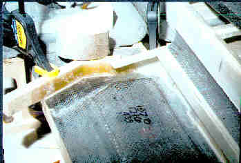 |
Starting the initial layup The molding faces of the form boards were covered with packaging tape as a release agent and the initial layers of cloth were laid up directly against them, lapped up onto the outboard side of the remains of the original rib, and simply butted to the lower skin. This BID layer was 6 plies thick and the micro-balloon fillet that allows a smooth transition from vertical to horizontal for the subsequent plies has been applied to the lower corner. |
|
The next layer With the first 6-BID trimmed down to its approximate finished size, the next 6-BID layer which ties it to the bottom skin is applied. |
 |
|
 |
 |
|
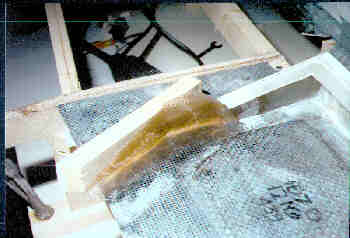
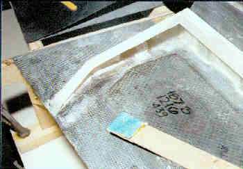
Lower layups complete With the rib built up to 12 thicknesses of cloth it is trimmed to the approximate airfoil shape and then microfit to the upper skin in preparation for the addition of the upper capstrip. Here it is just before the microfit. (BTW, a 'microfit' is accomplished by applying a layer of flox along the upper rib edge and then molding it to the inner surface of the skin to which as many plies of duct tape release as it takes to make up for the thickness of the subsequent capstrips has been applied. Works like a charm.) |
||
 |
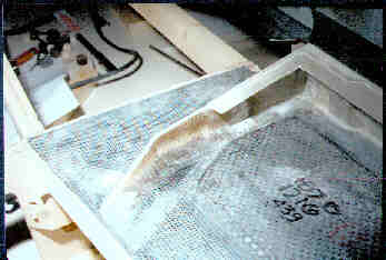
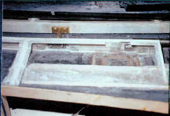
Completed BL3.2 rib The upper 2-BID capstrip has been reapplied, an additional 2-BID layer ties it to the inboard face of the new rib, everything is trimmed to size, and the repair to the rib is completed. The final BID layers will be added to the inboard side after the elevators are closed and the rudder clearance notch has been cut. Now it's time to get back to that spar problem..... |
|
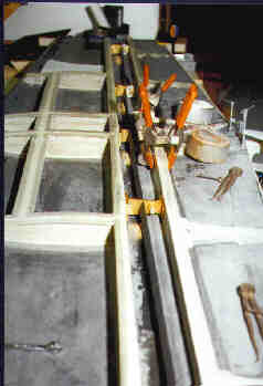
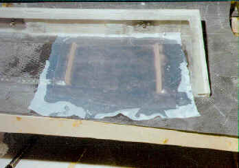
Aligning the elevator to the stabilizer Looking at the inboard forward face of the left elevator's spar (the elevator is pictured to the rear), the pads required to achieve the alignment between the two components can be seen. The dimensions that were taken and the fit being achieved between the elevators and the stab required that the left elevator sparface be built out at the inboard end slightly to accommodate the hinges and get them aligned with their brackets. The corrections here were fairly minor and took into account not only the spars' misalignment but differing heights in the forward faces of the elevator control weldment's mounting brackets. Once again the required buildups were accomplished with BID layups instead of using simple flox pads. |
 |
|
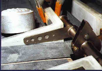 |
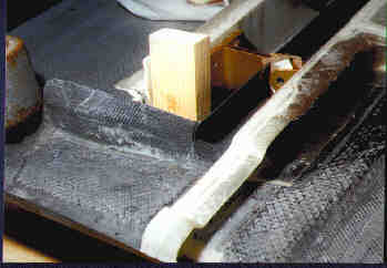
Checking the fit of the left weldment arm With the front mounting tab of the left elevator control weldment clamped tightly to the sparface it's apparent that the spar is leaning back slightly, as the end of the weldment arm is nearly touching the bottom skin. (The right weldment arm was centered on the BL3.2 rib when it was similarly clamped in place, so the sparfaces were vertically misaligned.) Since the weldment mounts through both the sparface and the BL3.2 rib at a right angle relative to each other, and because the mounting is mirrored on both elevator halves, the offending part would need to be corrected before proceeding any further. It was decided to once again stagger a few more layers of cloth at the top and to grind away a small amount of the earlier BID layup at the bottom on the left sparface to achieve the proper vertical alignment with the right side. |
|
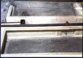
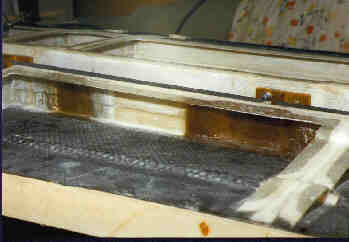
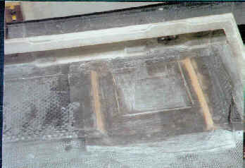
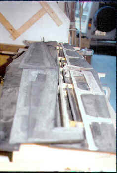
The view from the rear Looking at the back of the right elevator spar with the elevator firmly affixed in its proper location relative to the stabilizer you can see the cutouts that were made in the sparfaces to allow the hinges to sit further back relative to the leading edge. As it worked out, the sparfaces had to be removed completely for the outboard hinges on both elevator halves and for the middle hinge on the right side. The inboard weldment mount on the right required removal of some material (it only needed an extra 1/16",) but not all. The center hinge and weldment mount on the left half both needed to be shimmed forward. |
 |
|
 |
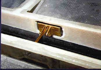
Center right hinge, rear view This view shows the amount of clearance that was allowed around each hinge so the closeout BIDs that would be added from the front wouldn't interfere with the final positioning of the hinge itself. The corners were left nice and round so the cloth would form to the area without wrinkles, and the entire perimeter was pre-bevelled so the need for filleting material (micro) would be kept to a minimum. |
|
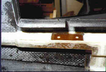
Center right hinge, front view The view from the front of the center right hinge once again, showing the clearance visible from that side, as well as the tape that was put on the hinge mount to act as a release during the layup process that was soon to follow. The little rough ridges surrounding the hole were removed during the prep-sanding that was done to ready the spar for the new fiberglass that was to be added. |
 |
|
 |
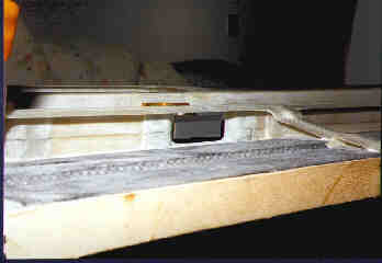
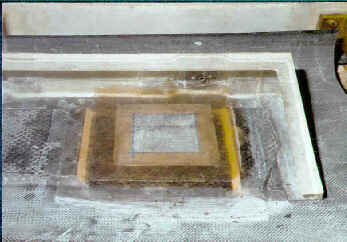
Final clamping, ready for layups With both sparfaces prepped for their new BID hinge-mount additions, all the dimensions are triple checked and everything is clamped tightly to the fixtures so nothing moves during the layup process. If you look closely at the hinge that's pictured to the immediate left of the top end of the front spring clamp's handle you can see what looks like a white square sticking out from where the hinge mates to the hinge bracket. That white card is a spacer made from formica that held the hinge in position on the bracket... since the backs of the hinges were actually acting as molds for the layups they had to be immobile, and the little laminate cards did the trick. |
|
A completed layup Once again using the right elevator's center hinge as the subject, the initial layups have been completed and covered with peel-ply. (Peel-ply is a finely woven dacron material that doesn't stick to the epoxy and as such is removable. When the layup has cured and the peel-ply is removed it leaves an imprint of its weave on the surface which is adequate preparation for subsequent layers.) In this instance the peel-ply was used to provide not only a good bondable surface, but to hold down the edges of the BID and provide a smooth transition to the adjoining area. This layup was done in several layers all at once, as the final BID schedule was for a 10-layer laminate. (The material that had been cut away was originally 2-BID prepreg, a 6-BID wet layup, plus 2-BID tying in the capstrips on top and the skin on the bottom.) |
 |
|
 |
Minor mods to the LE The elevator's leading edge radius needed to be reduced ever so slightly to fit and rotate properly between the stab's TE at the outboard end, so the molded part was cut and braced backward a bit then bonded back into its new position with a 2-BID layup from the inside. I could have just lived with it but found that I'd have had to build up the stab's TE with filler at the outboard end about 1/32" top & bottom to make it match, so decided this was a more weight-conscious means to the same end. |
|
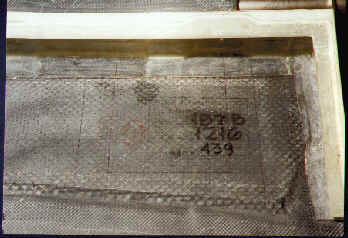
Inboard rear of the right elevator Since material had to be removed from the weldment mounting area on the right elevator half's sparface, the BID schedule still needed to be complied with so the additional layers of cloth that were added to the back of the spar to make up for it can be seen here (layup to the left). Additionally, the peel-ply has been removed from all the layups in preparation for the addition of the nutplate pads. |
 |
|
 |
Ready for the front layups With everything disassembled, the hinges were left attached to the new layups and using their bases as patterns, the mounting holes were drilled in advance of doing the closeout layups that were to be added to the sparface. A single-BID layer was going to be added to the front of each hinge mount in advance of the final 1-BID that would tie the front surface of the spar to the LE skin. This gave me the opportunity to insure that I had a good fillet of micro at each newly made sparface location and bonded the new layups from the front of the spar as well. |
|
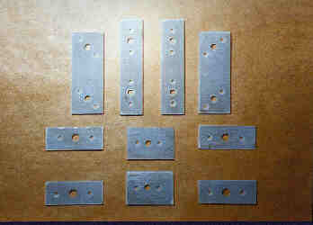
Nutplate pads for the hinges Once again I was faced with the same problem of how to apply the nutplates in a spot where I couldn't fit a rivet squeezer, so additional nutplate pads were fabricated to do the job. The long ones were for the hinges and the short ones for the weldment. |
 |
|
 |
Trial fit of nutplate pad Each nutplate pad was run down tight to the back of the spar to insure that it would seat perfectly flat against it during bonding. As you can see, a small amount of glass had to be removed from the new layup at very ends of the card to get this one down, even though the edge of the card had been radiused to fit. Once all the cards were fit tightly to the spar they were subsequently mounted permanently with Hysol structural adhesive. |
|
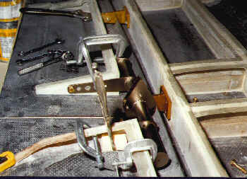
Final attachment of the elevator weldment With everything on the elevators now properly aligned, both halves of the elevator control weldment are clamped into position to facilitate the drilling of the mounting holes. It took a bit of fiddling to get both elevator halves to align, as the pad that had been built up on the left elevator sparface was slightly out of plumb and needed to be fixed to allow the skin to sit flat on the fixture. This photo was taken after the repair had been made and the aft bolt hole was drilled in its proper location. The next steps were to disassemble the weldment, drill the rest of the holes, and mount the nutplate pads that secured the weldments to the spars and the BL3.2 ribs. |
 |
|
 |
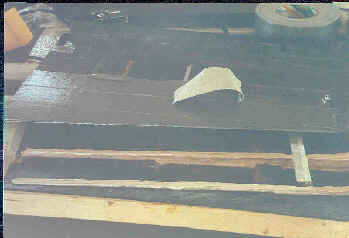
Laying out the trim motor access panel Now that the mounting of the elevator hinges and weldments has been accomplished, the next process is to deal with the trim motor access panel. The kit allows the builder to choose between alternative trim systems, either a mechanical one that becomes part of the elevator control system, or an electrical one that uses a servo motor to activate a trim tab on the left elevator half... I opted for the electric trim. This photo shows the layout for the access panel that will be built into the bottom of the left elevator to provide a way to install and service the servomotor that would ultimately be installed. |
|
Removal of inner BID plies Even though the servo motor is relatively thin, the inside of the elevator will not accept it without removing the inner skin plies and the honeycomb core. Additionally, the access panel only needs to be about 1/16" thick, so the inner plies and core material where it goes have to be removed anyway. Here you can see the area after the inner carbon fiber skin has been cut away and the core has started to be removed. The carbon fiber was cut using a cutoff wheel in a Dremel tool and the honeycomb was cut through the resulting slots using a very thin razor saw. Ultimately all the honeycomb and its bedding epoxy will be removed revealing the two exterior carbon fiber BID layers. |
 |
|
 |
CLosing out the core and thickening the panel With the core completely removed and the skins facing the area cut to a 45 degree angle, a 2-BID layup was applied to both thicken the lower skin to stiffen the access panel and to closeout the area where the core had been removed. The tan color material you see facing the opening is a mixture of microballoons and epoxy. The white cloth material covering the layup is peel ply. |
|
Initial panel cuts The access panel is partially cut from the bottom skin. The cuts stop about 1/8" from each corner so the mounting flange can be layed up against the panel itself, guaranteeing that the panel will mount flush with the exterior skin when it's reinstalled. The final cuts at each corner will be made after the mounting flange is installed. |
 |
|
 |
Access panel mounting flange The entire interior surface of the access panel has been covered with clear packaging tape so the BID layups that comprise the mounting flange won't stick to it. The flange is an inch and a half wide and was laid up in two separate layers, with the tapes overlapping the full width at each corner. It probably would have been quicker to simply layup a solid 2-BID square over the panel and cut away the center after cure, but I chose to follow the instructions in the manual and do it this way instead. Next time I have to do an access panel I'll probably take the faster route. |
|
Installation of trim tab spars At this point the manual suggests that the elevator be closed out, the trim tab be cut from the elevator and the small spars that keep the airfoil shape be installed afterwards. After talking this part of the project over with several other builders I chose to take a bit of a different approach. Rather than trying to fit the spars into the tab after it's cut away I decided to fabricate and install them into the elevator structure first. This way the airfoil shape could be maintained with the parts still mounted to the cradles, and make possible the the installation of the inner BID plies with the spars readily accessible. The spars are positioned far enough apart to allow for the mounting of the trim tab hinge to the inner upper skin surface. (Pardon the photo, but the flash synch on the camera decided to go intermittent and I didn't notice that the flash failed to go off for this and a few other shots.) |
 |
|
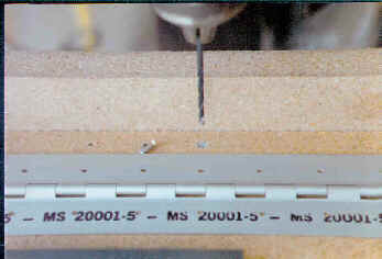 |
Drilling the trim tab hinge While I was waiting for the micro to dry on the top of the trim tab spars I chose to fabricate the hinge that would allow the tab to move. It was recommended that the #40 rivet holes be spaced every inch along the entire length of the hinge and this is the fixture that was used to accomplish that task. The fixture was nothing more than a couple one foot lengths of particleboard assembled into an "L" shape that aligned the far edge of the hinge along the back and provided a surface into which to drill. I have an indexing table mounted to the drill press (see the shop page about that setup) and after installing a rivet in the first hole, indexed the entire assembly one inch to the left and drilled the second hole. I made one additional leftward move and drilled a third hole (just in case the rivet hole got sloppy along the way) then simply inserted the rivet into the last hole drilled in the hinge and into the previous index hole, so from that point forward all the holes would be precisely located on one inch centers. After drilling the entire first hinge half the hinge was folded shut and the last hole drilled was used to locate the first hole on the second side. This way all the holes were precisely located directly across from each other on both halves of the hinge. |
|
After microfitting the spars Here you can see the layers of duct tape that were applied to the top skin to simulate the thickness of the 2-BID capstrip that would shortly be affixed the the spars. The whole idea here was to simplify the installation of the BID tapes that would need to be applied to achieve the correct thickness of the trailing edge of the elevator and the leading edge of the trim tab to allow the hinge to mount and finish out flush to the outer top skin surface. Additionally it was far easier to tie the spars to the capstrips while the entire area was open and held in shape by the building fixture. |
 |
|
 |
Trim tab capstrip applied The large capstrip in the trim tab area is cured and prepped for final closeout of the elevator. If you look closely you can also see that the upper capstrip on the front (main) spar has been cut away slightly to allow for the placement of the trim motor mount. The servo motor needed to be mounted that far forward to allow it to fit between the elevator skins without contacting the access panel at the rear. |
|
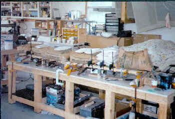
Final preparations to close Everything is prepped for the final closeout of the elevators, all the capstrips and interior top skin surfaces have been sanded and cleaned with methylene chloride to insure that there was no stray grease or body oils present that could destroy the bonds on any of the mating surfaces. The hinges and weldments are still attached to keep everything in shape, the cradles have been beefed up with additional blocking to help support the weight that was going to be applied to provide the pressure to the bonds, and all that's left is to mix up the structural adhesive and do the deed. This was truly a milestone in the building process, the first of many that were yet to come. |
 |
|
 |
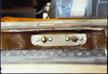
The view from the end The nutplates holding the right elevator weldment are visible and the triangular shape of the trim tab /elevator junction can also be clearly seen. Considering the diminutive sizes of the tab spars and their inaccessibility into the closed out areas once the elevator skins are final bonded, this approach allowed me to get at them both front and rear to tie them to the skins and insure that the airfoil shape was maintained throughout the process. This was the last time I'd get to see the inside of the elevators, and so a thorough inspection was performed to insure that nothing was forgotten and that every step in the manual had been accomplished or provided for. As they say, this is for all the marbles so everything needs to be perfect before proceeding. |
|
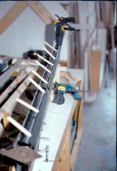
The elevators are closed at last The elevator closing consumed some 180 grams of structural adhesive, not counting that which would be used to bond the leading edges. A thin coating of straight Hysol was applied to each of the mating surfaces and then flox was mixed into the remaining material and mounded along the centers of all the capstrips to insure a solid structural bond and provide the required squeezeout between the parts. Once the skins were seated and verified to be in their proper locations, sandbags were placed over the entire structure to hold everything in place and apply the necessary pressure to the bonds during cure. The trailing edges were captured between the cradle and aluminum flatstock and were held tight with the bevy of clamps that are visible here. There's a total of 360 pounds of sandbags shown here, 5 sixty pounders in their original state and another 60# worth in one gallon size ziplock bags. The density isn't anywhere near what could be achieved with shot bags, but the cost was a fraction of what it would have taken to do the job with lead shot... 360 pounds of sand cost me $18, but a similar amount of lead shot bags would have run almost $200. |
 |
|
Bonding the leading edges The next day the elevators were removed from the cradles and their leading edges were bonded with structural adhesive as well. Here you can see the popsicle sticks that were used to pry the upper skin's LE away from the lower to allow the insertion of the structural adhesive. You can also see a quick-clamp applied to the counterweight area at the far end of the elevator providing pressure to get the outboard edges of the counterweight area aligned and bonded. Prior to applying the Hysol a series of 3/32 holes were drilled all along the leading edges to allow for the insertion of clecoes that would hold the mating surfaces together during cure. |
 |
|
... Building the trim tab |