
Setting up shop

Along with some details of the shop setup I'll be including photos and commentary on the various fixtures, tools and equipment being used to make it all happen. Keep checking back for regular updates.
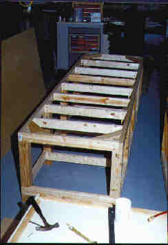 |
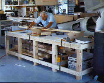
The building bench.Here's the basic framework of the building bench. The uprights are 4x4 southern yellow pine which have all been dadoed to accept the 2x4 perimeters and cross members. The 2x4 stringers used to support the top are on 14" centers to give it plenty of stiffness. The overall dimensions are 120x36x30, and the work surface is 3/4" particleboard which has been finished off with plastic laminate for durability. No pics of the finished bench without anything going on on top of it, as you'll be seeing it in use constantly throughout this site. A few construction notes... all of the components were glued and then screwed together. Initially there was no provision for levelling, but since the floor of the shop isn't perfectly flat, the need to deal with an uneven surface became obvious. There are 5/16" T-nuts installed into the bottom center of each leg and hex-head bolts are used as levellers to get the work surface perfectly flat. While the addition of diagonal cross members to the structure once levelled would lock in the shape, I opted against them to maximize storage space below. Besides, once the table is levelled in a particular location, the position of each leg is marked on the floor and returning it to that spot, should it move, becomes a relatively simple task. |
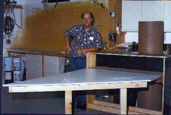
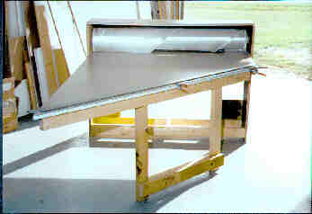
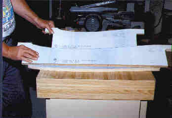
A cabinet and cutting table for the fiberglass.The table you see here also doubles as a cabinet to store the roll of fiberglass cloth to keep it clean and safe. The table top is cut on a 45 degree angle to provide me with a guide to insure that the fiber orientation in each piece of 'glass' is on the bias. The glass cloth is supplied with the weave 90 degrees to the roll, and having this angle on the front makes proper alignment a snap. |
 |
 |
 |
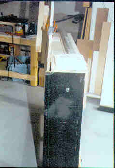
Here you see the glass cutting table in its closed condition, both from the end and from the front. The cabinet itself is only about 11" wide, and the top panel is cut slightly narrow to allow the work surface to rest tilted slightly back when closed (see left photo above.) This entire unit sits between the building bench and the shop's office back wall when it's not needed, conserving about 35 square feet of floor space. The legs hinge up against the bottom of the cutting surface (right photo) when in the storage mode, and fold down automatically when the cabinet is opened for service. (By the way, the lumber that was used here has already served other purposes, as the 2x4's were used as blocking and supports when moving the kit on the trailer, and the black sides were scrounged from an old bar-top removed from one of the local pubs.) If you look closely at the side view you'll notice a small silver cylinder centered on the side of the cabinet, about 5 inches down from the top... this is a 1/2" electrical conduit coupler which has been cut in half and used as the retaining sleeve for the piece of conduit which is used as the axle for the roll of fiberglass cloth. The cutting top is hinged with a continuous piece of piano hinge and the fold-down legs utilize standard 3" strap hinges. |
|
 |
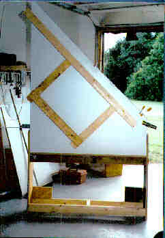
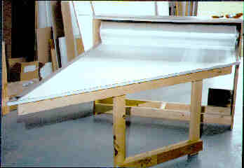
With the work surface hinged down the bolt of fiberglass cloth is visible and available for use. Rolling it back up after cutting is accomplished by rotating the retaining collars on either end of the axle shaft. Also visible here is the six foot long aluminum straightedge which is used as a cutting guide when it's time to cut a strip from the roll. The legs are positioned far enough back so the straightedge can be clamped to the cutting surface with standard spring clamps. I've applied strips of duct tape to the cutting surface to provide a cushioned surface for the roller cutter (looks amazingly like a pizza cutter, only much sharper), although one of these days I may switch the cutting surface to a softer plastic than the melamine laminate currently being used. It's too hard and doesn't allow the cutter to work as well as it could. So far the duct tape is doing the trick, so I'm not horribly worried about it. |
When the glass cloth is rolled out for cutting it is aligned with the long (left) edge of the cutting surface to insure that the fibers are all nice and straight. Any waviness in the long edge indicates that the fibers are misaligned and won't be cut at a true 45 degree angle when lined up with the front edge. Once the long edge is perfectly straight, the material is stretched from the cutting edge toward the back to align those threads as well. The material, once measured and cut, is then taken to the laminating surface for further processing. When all cutting is completed the material is rolled back up, the cutting surface closed and the entire cabinet put away to await its next use. The glass cloth remains completely protected from dust, dirt, and mishap. |
 |
I've had quite a few requests for a measured drawing of the cutting table, and have finally managed to pull a set together. I'm pleased to present them here along with a few extra building notes to try and clarify any questions you might have.
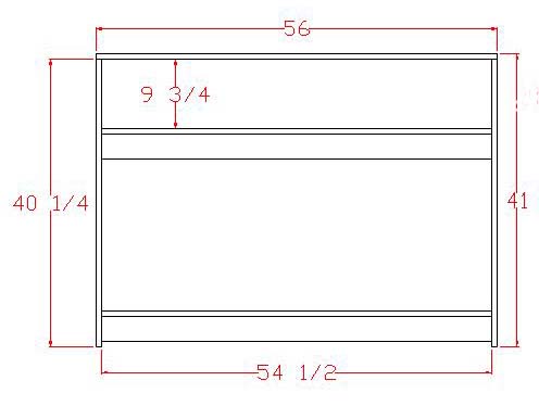
This is the basic cabinet construction. All of the panels are made from 3/4 plywood, although flakeboard could be used just as well.
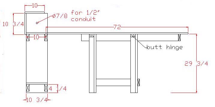
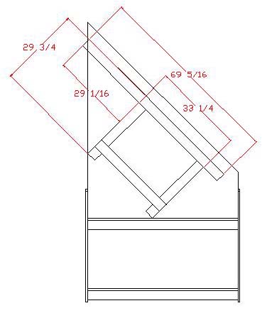
Here's a side view of the opened cabinet/table... all of the boards with the X's in them are 2x4. You can see the hinges mounted to the backs of the folded down legs.
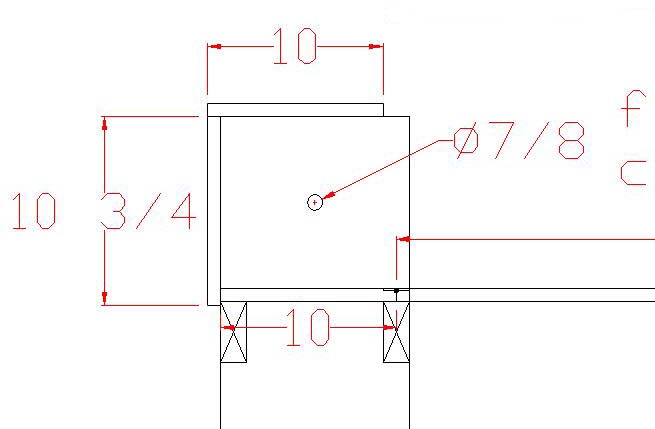
Here's a detailed blowup of the upper part of the cabinet. You can see where the hingeline between the cabinet shelf and the cutting surface is located, as well as how the various outer panels go together. The top cover is held back 1-1/2" so the folded cutting surface will lean back a bit when in the stowed position.
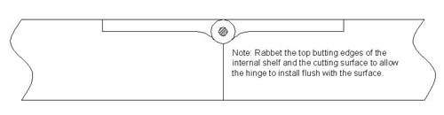
Here's a detail of the piano hinge which mounts the cutting surface. The hinge is mounted flush to the top, and on my table is actually covered by a sheet of formica. If you're using a high density polyethylene sheet as a cutting surface it will slide back into the cabinet much easier if this hinge is mounted flush.
Here are the leg dimensions, although they aren't critical. By the way, if you've got a low ceiling you might need to shorten the cutting surface or take another approach, as I did upon moving into a smaller shop. I cut the last foot of the cutting surface off and set it up with another flush mounted piano hinge. By pulling the hinge pin I can remove the pointy end of the cutting surface and then fold it up without it hitting the 8' ceiling. As shown the actual height is about 104".
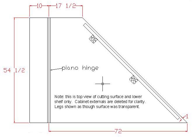
Here's a drawing of the cutting surface and the shelf it hinges from. You'll notice it's 54+ inches wide... this material is readily available from most cabinet shops. Remember, the bolt of glass cloth is about 52" wide, so a plain old 4x8 sheet of plywood just won't do the job.
 |
Cradles for the horizontal tailThese cradles are made from 1/2" particleboard and are used to support the horizontal tail throughout its construction. Duplicate full size templates are supplied with the prints so one page can be cut out and applied to the wood as a cutting pattern. The manual calls for 4 of the small (tip) cradles and 2 of the large (centerline) cradles so the entire stabilizer/elevator assembly may be clamped between them to verify shape and thickness. |
 |
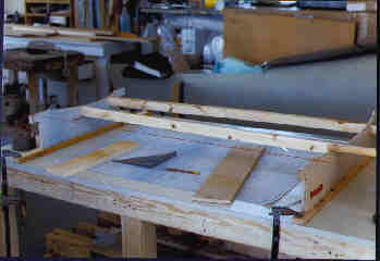 |
The cradles were mounted to 1x2" pieces of wood which spanned the bench and were used to clamp them to the top. Insuring that the distances between the cradles was very important, as they will define the ultimate shape of the horizontal tail when it's completed. It took some fiddling and fitting to learn that the outboard cradles needed be measured to their ultimate position based on their inside faces and not their centerlines, as was done with the middle cradle. The cradles are separated by 1x2 runners which will support the parts along their length as well. These runners were stapled and screwed to the cradles to insure that they stayed where they belonged. We left out the runners on the elevator portion of the cradle initially to provide unobstructed access to the stabilizer as it was the first part to be dealt with. The elevator runners were added at a later date. |
|
Keeping the dust downThis is a view into the container of my shopvac, to which I've made a slight modification to help keep the dust at bay in the shop. Shopvacs typically use a multi-stage filter around the motor, starting with a layer of foam, then a cloth bag followed by a paper filter element. I've found that even with all that filtration the very fine dust that results from sanding fiberglass components still manages to make its way through. And if it doesn't, it clogs those filters so quickly that it almost makes the vac a worthless device by drastically limiting the available suction . |
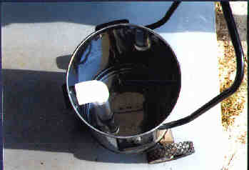 |
| What I've done here is cut the shoulder away from the inlet and attached a 2" PVC pipe elbow and a 2" PVC drop tube that reaches to within 1.5 inches of the bottom of the canister. For filtration I use only the foam filter and about 3 inches of water in the bottom of the canister, and to keep everything smelling clean I add about an ounce of laundry bleach to the water. No dust ever gets past the water, the suction is completely unrestricted, and all I need to do is dump it and rinse it out about once a week (depending on the amount of sanding being done.) Beats the heck out of pumping all that dust around the shop. (If you decide to do this, my only admonition would be that you don't cement any of the PVC components, just use a friction fit to hold everything together... this way when you suck up your favorite pencil there's a way to get it out of the drop tube. Additionally, be sure to check the dimension of your inlet, as it may be something other than 2". Taking the cutoff shoulder from the inlet on that shopping trip to the building supply store will insure you get an elbow that fits perfectly. ) |
|
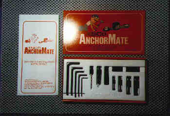 |
Nutplate drilling fixtureThis is a slightly different alternative to the nutplate drilling tools that are normally used. Instead of a small fixture mounted to a handle on a piece of spring steel flatstock which fits a single size nutplate, The 'Anchor Mate' by an Australian company called Esco (available from Lancair) includes fixtures for drilling K1000 nutplates in sizes -06, -08, -3, and -4. Included in the kit are a pair of hardened drill-guide fixture blocks, long and short hex head cap screws and coupling nuts in each of the four sizes listed, a #40 drill (with a standard 1/4-28 shank) and countersink for the rivet holes, and all the allen wrenches required to make the kit completely self contained. It comes in a very nice steel case and includes a set of instructions for use. A very handy tool indeed. (I'll get a better picture in here shortly... isn't flare a pain.) |
Working with the structural adhesiveIn addition to the liquid epoxy used to layup the fiberglass there is another type of epoxy used on this kit which is a bit thicker, mixes at a different ratio of base to catalyst, and as such requires the use of a scale and a calculator to insure the proper proportions are maintained. This material is called Hysol 9339, pictured here in the two cans to the left, the bottom can holding the base and the top one the catalyst. For small batches I use a pair of 20ml syringes to dispense the materials into the mixing cup. For larger batches I use 60ml syringes (not pictured) and for really large batches, a spatula for the base material and one of the large syringes for the catalyst. The syringes allow me to dispense the materials very precisely, and the use of the quad-beam balance scale gives me accuracy to 0.01 gram. (This might be overkill in precision for larger batches, but when mixing a small batch of 4-5 grams it's invaluable.) |
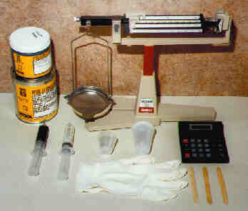 |
The procedure for mixing a batch of Hysol goes something like this... first ascertain approximately how much is going to be required to do the job, and once that's done, select a mixing cup adequate to the task. The cup is weighed and then filled with approximately 2/3 of the total material requirement in base (white) material. Once an accurate total weight for the cup and base has been determined, deduct the weight of the cup and multiply the remainder (weight of the base) by 1.445 (proper ratio is 44.5:100 catalyst:base). This gives a total weight for the completed mixture. Add the weight of the cup back into that total and set the resulting weight on the beams of the scale... catalyst is then added to the cup until the scale balances and the proper ratio is achieved. The rubber gloves keep my hands clean, the popsicle sticks (or coffee stirrers, depending on your point of view) work great as mixing sticks and as applicators. The little plastic cups are those which are used in hospitals to dispense medications and are readily available from the local pharmacy, as are the gloves. While the use of a balance scale may seem a bit archaic, this one was purchased at Sun 'n' Fun from one of the Fly Market vendors for about 1/3 the price of a new electronic scale with similar accuracy. The primary advantage to using an electronic scale would be in having the ability to zero the scale after the cup is on it, removing the need for dealing with the tare weight from the calculations. For the $100 I saved, I'll deal with the weight of the cup. |
|
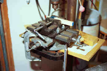 |
Index TableWhile it's not absolutely necessary, the addition of an indexing table to the drill press has turned out to be a real blessing. The unit pictured here isn't the quality of what you'll find on a Bridgeport, but for the small amount of precise drilling I'm going to be doing, it is certainly up to the task. When it was unpacked and initially set up I found that the backlash was almost a tenth of an inch, but with a little tweaking here and there I've managed to get it down to about 0.004... still not perfect, but as long as I remember to preload the table in the direction I'm going to be drilling it's pretty easy to maintain an accuracy of about +/-0.002". The addition of a 4" drill press vise to the top makes it a very workable combination and the size of the investment was really pretty modest. |
| I don't know whether I'd have invested in the index table had I chosen to purchase the bracket kit option offered by the factory, but since I didn't buy that package I knew that I was going to have to be fabricating about 50 different brackets and fittings and thought that this would be the easiest way to get the job done and be accurate with all the hole positioning. Since it's been in the shop, though, I've found that I've used it for much more than the bracket fabrication, and have come to rely on it pretty heavily for much of my hole drilling needs. I can also use it as a milling table, although with its lack of accuracy I don't know that I'd want to do any precise milling work with it. The total investment here, including both the index table and drill press vise, was about $130 plus another $12 for shipping, and so far it seems to have been well worth the money. Tools like this are routinely available from industrial tooling and cutting supply companies, and a call to a local machine shop should put you in touch with their tooling supplier. If you'd like further information on this particular setup or would like to purchase one, feel free to email me for the details. | |