I chose to start the construction process with the horizontal tail. While this may not have been Chapter One in the manual, it is a smaller subassembly and one that could be worked on without consuming a lot of space. There were a number of new skills that needed to be learned for me to successfully complete this kit, and my main goal starting here was to be able to get the feel for working with the materials on something smaller than the fuselage. The processes will remain essentially the same throught the aircraft's construction, but at least with this particular component most of the layups would be small allowing me to get a better grasp of handling and applying the fiberglass cloth and epoxy. Additionally the hardware requirements were fairly minimal and the only component that had to be purchased to complete the entire subassembly was the servomotor for the trim tab. Consequently this part of the project should progress at a reasonable pace since just about everything required was already in the shop. The original Lancair 320/360 included a smaller horizontal tail, one that spanned approximately 76 inches, and was made from the same e-glass prepreg materials as the rest of the kit. Several years ago, however, the company chose to enhance the stability of this aircraft with the introduction of a new, larger tail which spanned about 96 inches and was made from carbon fiber to save weight. They called this improved tail the 'MKII', and is the one that was included with this kit. Additionally I chose to avail myself of their 'Super Fast-Build' option in which many subassemblies were completed at the factory, giving me a leg up on the time that should be required to build the kit. While it's suggested that this 'SFB' option should cut about 1,000 hours out of the construction process, I guess we'll have to see for ourselves... |
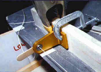 |
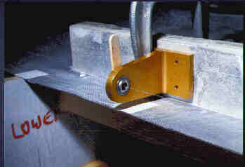
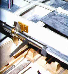
Initial hinge bracket alignment... Once the stabilizer was secured in the cradles the first step was to start the alignment of the hinge brackets that would be attached to the stab's aft spar. This is the bracket at the far left end of the stab. It is temporarily clamped in place and we've run a string through the center of its bearing and through all the other bearings to see just how well the brackets lined up. Needless to say, doing this with a string this thick was almost a wasted effort as the center of all 5 hinge brackets need to be in a straight line and finding out whether they all really lined up this way was truly asking too much, the margin of error was too great. |
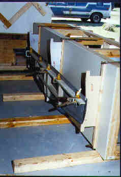
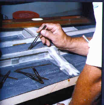
Bench and work rotated 90 degrees Checking and rechecking the hinges appeared to be the only way to go. Here we had rotated the bench backwards 90 degrees and were reverifying the heights on each and every bracket. By this time I had switched to monofilament line and found that by using a dial caliper to measure its position relative to the hinge base or the skins I could easily see a discrepancy of .005-.010". I simply did whatever was necessary to get the hingeline to pass straight through the center of each bearing. The reason that hinge axis concentricity is so important is that it prevents binding and allows for free movement of the control surface. |
 |
 |
Filling the low spots Once all the measurements were taken and the low points in the spar located, pads were built up under each hinge bracket to raise them to their required location. The pads were built using a filler made from a 50/50 mixture of flox/micro-balloons in epoxy, and the cards you see bordering each of the hinge locations were used as forms to establish the proper depth of the filler. Once the material had hardened it would be easy enough to simply sand to the final height to get the proper horizontal alignment of the hingeline |
| Pads are complete, rechecking dimensions The pads have been sanded to their proper heights, the hinges reattached, and measurements resume. |
 |
 |
Much more precise... As you can see here, the monofilament line being only .010" thick really allowed me to get the kind of precision I was after. The addition of the flox pads extended the sparface to a common line along its length, but I discovered that it was also slightly out of plumb. By aligning the hinge bases' vertical centers with the spar's centerline I should have had the hingeline running straight in both the vertical and horizontal dimensions, but I didn't. The possible solutions were to mount the brackets slightly off their vertical centers, or to rebuild those pads and correct the angular misalignment... I chose the latter. |
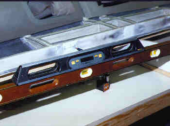
Rechecking the level of the cradles Just to be sure that something else wasn't wrong I rechecked the level of the cradles to insure that the stab was still being held in the proper alignment. If it was bent by the cradles being mispositioned it would give me similar vertical misalignments. This step verified that the cradles were, in fact, perfecly level, the stab hadn't moved, and that the problem had to be with the spar itself. This was just to be sure that I wasn't going to be fixing the wrong thing. |
 |
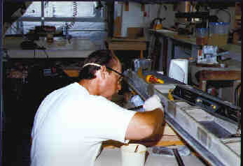 |
Applying the BID shims Here I am applying one of the BID (BI-Directional cloth) shims to get the sparfaces at each bracket perfectly vertical. The approach was to apply overlapping successively larger layups to each pad, building them out to the proper angle as required. The preliminary step to this was to ascertain the amount of buildup required by using the smart level and feeler gauges between it and the spar to get it to read plumb. The amount of displacement at each location was noted and the appropriate layup applied. Each layer of cloth would add right around .010" so if a given pad required to be built out 1/16" at the top tapering to zero at the bottom it meant that six BID layers would be applied, the smallest at the top, followed by another slightly larger, and another larger yet, etcetera, until the final full width tape would cover them all. It worked like a charm. (Using BID layups instead of simple flox pads was suggested by a fellow builder I know from Compuserve's AVSIG forum, and a fine suggestion it was. Thank you, Tom Navalenko, Stallion builder.) |
A completed BID pad Here is what a completed pad looked like. The advantages to using the fiberglass cloth as opposed to a simple flox buildup were increased strength and controllability of thickness. It was a simple matter to apply the numbers and get the pads doing exactly what was intended. |
 |
A "K1000-3" Nutplate At this point it was necessary to start thinking about providing for the final attchment of the hinge brackets to the stabilizer's spar. Once the assembly was closed out there would be no access to the stab's interior, so the use of blind mounting nuts (nutplates) was specified. These attach with a pair of rivets through small ears that extend from the nut portion of the part. The problem I was running into was that the capstrips on the spar wouldn't allow me to get a rivet squeezer in there to properly form the rivets and attach the nutplates, so a different approach needed to be taken. I chose to build fiberglass cards to which the nutplates could be mounted, and the cards subsequently attached to the back of the spar using structural adhesive. |
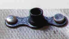 |
| (For those of you out there who don't know a nutplate from a frammis, this is what one looks like. Additionally I was in the 'experimentation' mode when I attached this nutplate to the small card you see here and used two different squeezing dies to see what the results looked like. The rivets are formed correctly with the flat die as seen pictured here on the right side.) | |
 |
Making the 6-BID layup The first step in making the cards to which the nutplates would be mounted was to fabricate a sheet of fiberglass material from which they would be cut. The layup seen here is 6 layers thick bi-directional cloth (called a 6-BID) and was weighted down with a board with several pounds of lead to squeeze it good and flat. The roller was used to remove all the air bubbles from between the BID plies, the entire layup done between 2 sheets of facing plastic (Visqueen) to keep the entire thing from sticking to the bench or the weighted board. After it had cured it was sanded to a constant thickness (about 0.060"), and cut into individual 1.5x2.5" cards. |
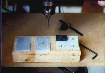
Machining the nutplate cards Once the 6-BID layup had been sanded and cut into appropriately sized cards to which the nutplates could be mounted, they needed to be machined for the nutplates themselves. Here you see an original card without holes, a card with the four primary bolt holes, and lastly one with the rivet holes drilled. The black part attached to it is actually the drilling fixture which is used to precisely locate the rivet holes. More information about this tool is available on the Shop page. |
 |
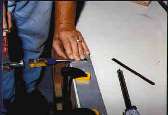 |
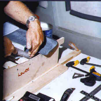
Using the 'Poor-Man'sRivet Trimmer' The accepted specification for rivets that are to be used to secure two parts together requires that the exposed rivet shank (the part to be formed) be 1.5 X shank diameter. This is to insure that after the rivet is formed the finished specifications will also be met. I discovered that the rivets I had were about 1/16" too long so they needed to be trimmed before use. Since I didn't have a real rivet cutter I decided to improvise and turned a plate of 1/4" aluminum and a chisel into a rivet trimmer. Several #40 holes were drilled and then countersunk to match the rivets, the rivets were then inserted into the holes and the entire assembly clamped to the bench with the shanks pointing up. By using a standard carpenter's chisel as a cutter and holding it tight to the fixture I found that I could trim the rivets to the precise 1/4" dimension required by this particular installation. A solid tap with the hammer and the rivets were cut off nice and clean. Sooner or later I'll probably have to think about a real rivet trimmer, but for now, this seems to be doing the trick. |
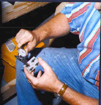
Checking the completed nutplate cards After the nutplates had been mounted to the cards it was time to insure that all the rivets met the finished specification. The diameter of the formed rivet head must be no less than 1.5 X the shank diameter, and the thickness of the formed head at least 50% of the shank thickness. Here I am using my trusty dial caliper to verify that all these dimensions have been met. Call it beginner's luck, but I found that every single rivet was formed according to spec, so I was able to accept the entire batch without having to replace a single one. (I did work slowly toward the specification with the rivet squeezer on a practice card, and it was well worth taking the time to do so.) With the nutplate cards completed I then remounted and drilled for all the hinge brackets and mounted them in what would be their final location. |
 |
 |
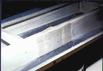
Prepping for stiffeners In order to ascertain precise dimensions between the upper and lower skins of the stabilizer's trailing edge I decided to add a single 1" wide layer of fiberglass to both the inner and outer surfaces of both skins. (Ultimately the TE (trailing edge) will receive a 3-BID closeout layer, but until then the skins were too flexible to get consistent dimensions, so this step was taken.) The light grey area you see here is what the skins looked like after they were prepared for lamination with 40-grit sandpaper and then thoroughly cleaned with methylene chloride. The roughing with the sandpaper insures that the epoxy will have a good toothy surface to which it can adhere, and the methylene chloride removes any grease or dirt that might affect the bond. |
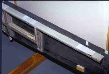
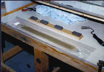
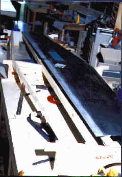
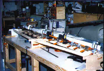
Plenty of clamps! With the layers of fiberglass cloth applied to both the inner and outer surfaces of the skin the enitre assembly is clamped between lengths of aluminum angle and flatstock to help hold everything straight and true. Prior to applying the aluminum stiffeners the layups were covered with a layer of visqueen to keep them from sticking to the aluminum. Once cured, the trailing edges were much stiffer, completely wave-less, and ready to give up their final dimensions. |
 |
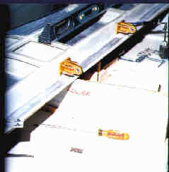 |
Final alingment and drilling for hinge brackets Satisfied that everything on the stabilizer's spar is in proper alignment the hinge bracket mounts are drilled first with an 1/8" drill bit and then clecoed in place. With all the brackets aligned and checked one last time for bearing concentricity, the holes are enlarged with a #30 drill in preparation for final attachment with the AN3 bolts. (The bill of materials calls for AN3-5A bolts to secure the hinge brackets, but because the aft face of the spar was built up in several places and the nutplates were mounted to separate cards instead of directly to the spar I found that I'll be using AN3-7A bolts instead to attach the hinge brackets. The -5A bolts do not provide me with the required minimum of 2 threads showing from behind the nutplates.) |
Making room In order to fit the elevator weldment to the center hinge bracket it was necessary to slightly modify the center stabilizer cradle. The location of the weldment was marked on the cradle, the stab removed and the cradle cut. The stab was then reinstalled into the cradles and the elevator weldment attached. The center weldment locates the elevators in their final position, so it is imperative that it is able to be mounted to the stabilizer for all final dimensioning. |
 |
 |
Counterweight cutouts The next step in the process was to provide the final cutouts in the outboard ends of the stabilizer to allow for free movement of the elevator counterweights. The positions of the cutouts were marked on the skins and then cut with the Dremel tool mounted with a cut-off wheel. Since the cut-off wheel couldn't get right up tight to the ends of the spar a hobbyist's razor saw was used to finish the cuts and then everything was cleaned up to the final dimensions with a file. |
Notching the elevator leading edge With the hinge brackets attached to the spar it's now time to get the LE of the elevator notched to allow the hinges to be mounted. The locations of the brackets were marked onto the LE and a Dremel tool / cut-off wheel was again used to cut the initial notches. They were then finished off with a file to achieve the final fit. |
 |
 |
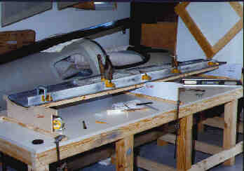
Verifying the elevators' alignment With the elevators now able to be positioned behind the stab the task of verifying their alignment commences. I find what appear to be some minor discrepancies between where the hinges are supposed to mount on the elevator spars and start thinking that perhaps all I'll need to do is some more shimming and all will be well. Unfortunately that was not the case. After discussing the discrepancies I was seeing with several other builders who had already completed this part of their project I decided that the spars were mislocated and would require modification to get everything to fit up and align to the stab's TE with the proper gap. Using my CAD drawings for guidance I compared the distances from the sparface to the outside of the leading edge at each hinge location and found that the spars were apparently 1/4" too close to the leading edge at the outboard ends, and varied slightly as I went inboard from elevator half to elevator half. Deciding exactly how to correct the discrepancies took up a bit more time than I had anticipated, so I moved on to other tasks before continuing. |
Early on in the manual it is recommended that the trailing edge of the stabilizer be trimmed to the dimension called out in the plans, that being 2-1/8" behind and parallel to the stabilizer's aft spar. Dutifully following that direction and paying close attention to the admonition that it is imperative that the trim line be perfectly straight from tip to tip, I cut the skins as instructed. What I didn't know was that one of the tricks suggested by the factory is to skip that step, and to first fit the elevators to the stabilizer. Only when the elevators are hinged as required should the upper and lower stabilizer skins then be cut back until the specified 0.050" gap is attained, irrespective of whether the stab's trailing edge line remains straight from end to end. Using their (unofficial and unpublished) method, the trailing edges will be straight relative to each elevator half, but perhaps not so from tip to tip. This really doesn't appear to matter as the stab's trailing edge line is not continuously visible from either end once it's assembled to the airframe, as the vertical fin is mounted directly over the center and obviates the possibility of sighting down the trailing edge to verify its linearity. Little did I know that starting with that straight line and then trying to fit the elevators to it would cause all the work that I suddenly found myself faced with. I should mention at this point that once I'd trimmed those skins I took a series of measurements and created a complete set of CAD drawings of the elevator hinge areas to ascertain exactly where the elevators would need to mount to the stabilizer and have everything work. Utilizing several 'fixed' dimensions (such as the location of the hinge line which is set by the hinges and hinge brackets, and the distances between the upper and lower skins at the stabilizer's trailing edge) my drawings told me exactly where the elevators' spars would need to be located to allow the elevators' leading edges to rotate freely within the confines of the stab trailing edge. All subsequent steps dealing with the elevator spars were taken to meet my drawn and calculated specifications. |
|
... The Elevators |